FEATURES & BENEFITS
Various Sizes
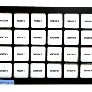
Various sizes are available from 8 to 64 alarm points.
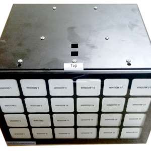
Dimensions are as follows:
Layout size (16 to 64 alarm)
- Height: 143 mm
- Wide: 30 x n + 25 mm
- Deep: 170 mm
Cutout size (16 to 64 alarms)
- Height: 130 mm
- Wide: 30 x n + 10 mm
Fully Field Programmable
The flexible design allows the selection of a range of features and a choice of operational alarm sequences compliant with ISA S18.1 1979. Alarms can be set to operate from either a normally open or a normally closed volt-free signal contact.
Connections
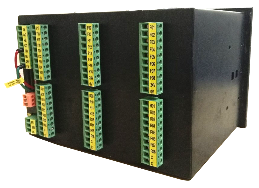
All connections are made on the rear of the unit using two-part quick disconnect rising clamp terminals accepting up to 12 AWG (2.5mm2) wire.
Inputs
All inputs are optically coupled and comply with the stringent requirements of the European Electromagnetic Compatibility and Low Voltage directives. The standard input voltage is 24VDC.
Common Outputs
As standard, each unit is fitted with three common relays: Critical Audible Relay, Non-Critical Audible Relay, and Common Alarm Relay. The common alarm relay is equipped with a reflash feature to indicate the occurrence of a new alarm within the unit
Auxiliary Relay
Each channel has an integral relay facility, typically used to initiate inputs to third-party devices such as RTU, SCADA, or DCS systems.
Integral Redundant Power Supplies
To maintain the highest level of reliability in safety-critical applications, all models are equipped with integrated dual power supplies. The standard unit is equipped with one fully isolated universal input supply, each capable of accepting either 110-250VAC/VDC. As an option, the secondary supply can be suitable for 24VDC if specified at the time of order.
Configure alarm way (Horn, Bell)
All alarm ways are configured by pushbutton controls Test, Accept, Reset, and input Configure (input Configure connect to customer terminal or Configure pushbutton)
To enter configure setup alarm ways, press and hold the pushbutton ACCEPT first and active input CONFIG together for 5 seconds (see connection diagram)
The lamp panel will light steady and the lamp first is light flashing. Parameter number 01 is selected.
Press the pushbutton ACCEPT to configure the alarm way (Horn, Bell)
+ Default is Horn
+ One pressing is Bell
+ Two pressings are Horn and Bell
+ Three pressings is no Horn, no Bell
+ Four pressings are returned Horn
Press the pushbutton TEST as function DOWN and RESET as function UP to change other alarm ways that are needed to configure.
To exit setup with store configure, press and hold the pushbutton ACCEPT first and active input CONFIG together for 3 seconds.
To exit setup without store configure, active only input CONFIG.
Auto Accept Timer
In unmanned applications it is common to have an automatic accept facility after a pre-set time, typically one minute; this is a standard feature on the MEEKA-AN.
Horn and Bell output are fitted as standard and each pair of alarm ways can be selected to operate either a critical or non-critical integrally mounted horn output. In substation applications, it is common for one extension relay to be used to operate the externally mounted station Horn and the second extension relay to be used to operate the externally mounted station Bell. Input response standard, The input response is set to 2ms for optimum performance, however, this delay is user-programmable and can be reduced or extended to suit the exact site conditions.
Pushbutton Controls
Integral pushbuttons are provided for Test, Accept, Reset, and Configure (if any) which control the operation of the standard alarms within the instrument.
The two power failure alarms have their pushbutton control lines wired to Customer terminals for connection to remote Functional Test, Accept and Reset
Order code
MEEKA-AN-Vnn-ppp-xx-c
MEEKA–AN:
programmable alarm annunciator
– Vnn: version of MEEKA-AN
| ppp: power supply | – xx: number of alarm ways | – c: communication interfaces |
| – 024: 24Vdc | – 08 – 16 – 24 – 32 | – N: None |
| – 110: 110Vdc | – 40 – 48 – 56 – 64 | – R: Repeated relay |
| – 220: 220Vdc | – M: Modbus RTU |
Example:
MEEKA-AN-V02-220-32-R
CONNECTIONS DIAGRAM






Reviews
There are no reviews yet.